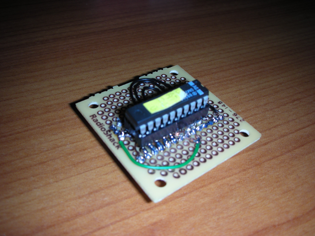
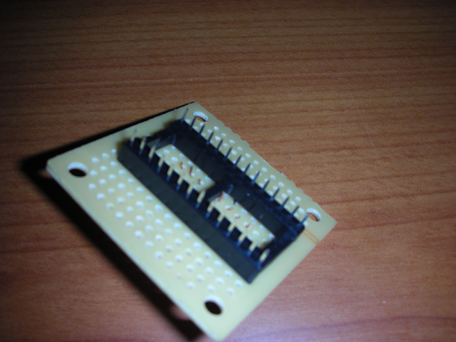
Originally posted by Stolistic on 12/30/2008:I built a crude example this afternoon to test my theory.
Its ugly but it works. After you read the CAP in, you need to trim everything starting at 0x200 to the end of the file, so all you have is 0x000 through 0x1ff.
If you are reading in a normal CAP you have to interlace a row of 32 0xFF's every other row starting at 0x020 and ending on row 0x1e0. (see
UPDATE below) I didn't read in a superboard prom (CAPX) but assume you would leave the data as is, making sure rows 0x100 to the end of file is all 0xFFs or all 0x00s.
Pictures are below:


Originally posted by 2Nutz on 12/30/2008:I built a crude example this afternoon to test my theory.
Its ugly but it works. After you read the CAP in, you need to trim everything starting at 0x200 to the end of the file, so all you have is 0x000 through 0x1ff.
If you are reading in a normal CAP you have to interlace a row of 32 0xFF's every other row starting at 0x020 and ending on row 0x1e0. (see UPDATE below) I didn't read in a superboard prom (CAPX) but assume you would leave the data as is, making sure rows 0x100 to the end of file is all 0xFFs or all 0x00s.
Sweet, I like the adapter to read the PROM's. Looks like I need to make a run to RatShack and/or HSC this weekend.
Confused on the rest of it though. On a regular CAP, after reading it with the adapter you install 2 rows of 0x00 to extend the data to restart at 0x40 for 2 rows and then 2 rows of 0x00 at 0x60, 2 rows of date at 0x80, etc ? This is necc. to make it read correctly once burnt onto a 27c512?
000: DA TA DA TA DA TA DA TA DA TA DA TA DA TA DA TA
010: DA TA DA TA DA TA DA TA DA TA DA TA DA TA DA TA
020: 00 00 00 00 00 00 00 00 00 00 00 00 00 00 00 00
030: 00 00 00 00 00 00 00 00 00 00 00 00 00 00 00 00
040: DA TA DA TA DA TA DA TA DA TA DA TA DA TA DA TA
050: DA TA DA TA DA TA DA TA DA TA DA TA DA TA DA TA
060: 00 00 00 .............................. . . ... . ..
Also, this process is not necc. for a CAPX and the data ends at 0x0ff ??
Just trying to get my few remaining brain cells around this.
:5- :47- :5-
Originally posted by Stolistic on 12/31/2008:Yes, you got the concept.
CAP Data after reading it in:
0000: 01 01 01 01 01 01 01 01 01 01 01 01 01 01 01 01 01 01 01 01 01 01 01 01 01 01 01 01 01 01 01 01
0020: 02 02 02 02 02 02 02 02 02 02 02 02 02 02 02 02 02 02 02 02 02 02 02 02 02 02 02 02 02 02 02 02
0040: 03 03 03 03 03 03 03 03 03 03 03 03 03 03 03 03 03 03 03 03 03 03 03 03 03 03 03 03 03 03 03 03
0060: 04 04 04 04 04 04 04 04 04 04 04 04 04 04 04 04 04 04 04 04 04 04 04 04 04 04 04 04 04 04 04 04
...etc...
CAP Data after editing:
0000: 01 01 01 01 01 01 01 01 01 01 01 01 01 01 01 01 01 01 01 01 01 01 01 01 01 01 01 01 01 01 01 01
0020: FF FF FF FF FF FF FF FF FF FF FF FF FF FF FF FF FF FF FF FF FF FF FF FF FF FF FF FF FF FF FF FF FF FF FF FF
0040: 02 02 02 02 02 02 02 02 02 02 02 02 02 02 02 02 02 02 02 02 02 02 02 02 02 02 02 02 02 02 02 02
0060: FF FF FF FF FF FF FF FF FF FF FF FF FF FF FF FF FF FF FF FF FF FF FF FF FF FF FF FF FF FF FF FF FF FF FF FF
0080: 03 03 03 03 03 03 03 03 03 03 03 03 03 03 03 03 03 03 03 03 03 03 03 03 03 03 03 03 03 03 03 03
00A0: FF FF FF FF FF FF FF FF FF FF FF FF FF FF FF FF FF FF FF FF FF FF FF FF FF FF FF FF FF FF FF FF FF FF FF FF
00C0: 04 04 04 04 04 04 04 04 04 04 04 04 04 04 04 04 04 04 04 04 04 04 04 04 04 04 04 04 04 04 04 04
00E0: FF FF FF FF FF FF FF FF FF FF FF FF FF FF FF FF FF FF FF FF FF FF FF FF FF FF FF FF FF FF FF FF FF FF FF FF
...etc...
I have not read in a CAPX (superboard) yet, so cannot confirm, but from what I've seen, it appears you just leave the data alone.
Have fun soldering and be sure to test all your connections for breaks and continuity before you use it. Post a pic if you get it working.
Originally posted by Stolistic on 1/17/2009:** UPDATE **I tested the adapter with a CapX chip and with a normal Cap and things work just great. However, my initial discussion about the non-CapX chips needing the data interlaced with FFs is INCORRECT. The data read in is in the proper order. So the reader works the same for both CAP and CAPX chips. No need to make edits afterwards.
Originally posted by Stolistic on 3/17/2012:I wonder if anybody has gotten this board to work, when I create my own schematic in Eagle Cad, I come out with a different layout. Is there something I am missing?
You schematic looks correct. I can see a mistake on mine what A5-A8 are shifted. The actual prototype I have does not have them shifted. It is just a translation problem to the schematic, which I believe I updated in a later revision. Good catch!
Originally posted by emm386 on 3/17/2012:Thanks for the quick response, I was going nuts when what I thought was right could be wrong! As they say, measure twice, cut once!
I am new into this stuff, figured the problem may have just been me and my lack of experience. I picked up a copy of Eagle Cad software and started learning the program. From what I see it is possible to make the unit support many different CAP PROMS if a few jumpers were to be added. Pins A9..A15 can all have jumpers. For instance if we place a tri-state jumper on A9 and ground A10 through A15, this should offset the memory by 512K. By changing the jumper on A9, back to ground, the unit should read the first CAP Prom's memory location. Here is a quick example of what I am thinking explained a different way.
Cap Prom # A9 A10 A11 Offset
0 GND GND GND 0
1 5V GND GND 512K
2 GND 5V GND 1024K
3 5V 5v GND 1536K
4 GND GND 5V 2048K
5 5V GND 5V 2560K
6 GND 5V 5V 3072K
7 5V 5V 5V 3584K
We could have many more CAP Proms on a single 512K chip if we placed more tri-state jumpers on the board, many more than proms than is on the market!
Note: I am pretty new at this so I could be wrong so don't take what I post as gospel concerning this information.
Originally posted by 2Nutz on 5/9/2012:You mean like this:
(SEE IMAGE ATTACHED TO THE BOTTOM OF THIS POST)Note: see attached .pdf file at the bottom of the post for settings for this pictured CAP adapter.Originally posted by 4 Deuces on 5/9/2012:HOLY ROLLER ... I DID IT!!
I am in
total gratitude for this completely awesome post!
I never imagined I could actually solder a circuit board, but after a little practice, checking it a gazillion times, I did it! In my continuity check, I found one connection that crossed, but that's because the wires got a little hot and joined, but as soon as I separated them, all was good.
I LOVE IT! I LOVE IT! I LOVE IT!
THANK YOU!! THANK YOU!! THANK YOU!!
Had to add pictures! I put a ziff socket on top to make it easier to change chips. Hope that's safe! (And yes, I plan to label the chip ;-)
(SEE IMAGE ATTACHED TO THE BOTTOM OF THIS POST)

 or just want to help support the site, please use this "make a donation" button:

 Home
Home Forum
Forum Help
Help Game Info
 Access levels
 Posting FAQ's
 Site Add-ons
 Media Gallery FAQ's
 NLG Terms of Service
 Search
 Contact
 Login
Login Register


